
Sceince And Technology of BIO-CNG Production
CBG generation involves four key steps, namely feedstock pretreatment, anaerobic digestion, biogas purification and compression.
Bio – Chemical scrubbing for H2S along with Water Scrubbing for Co2 provides the highest purity methane (> 98%) with minimum losses and power consumption during the upgradation.
Temperatures between 35–38°C and pH between 6.5–7.2, and C:N ratio of 30:1 have been found optimum for biogas production.
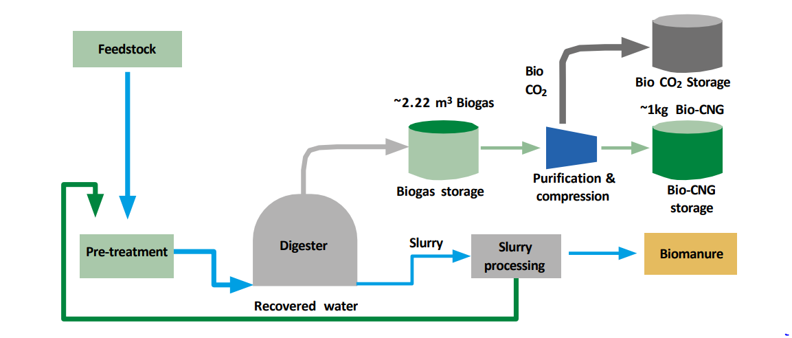
Biogas and CBG production efficiency of different organic feedstocks
| Feedstock | Feedstock Requirement | Biogas production | CBG production |
|---|---|---|---|
| Agriculture residue | 10 kg | 2.2 m3 | 1 kg |
| Pressmud | 25 kg | ||
| Sewage sludge | 20 kg | ||
| Bagasse | 10 kg | ||
| Municipal solid waste | 25 kg | ||
| Cow dung | 50 kg | ||
| Chicken litter | 25 kg | ||
| Forest residue | 15 kg | ||
| Napier grass | 10 kg |
Biogas: Technology for a circular economy
The process of anaerobic digestion uses various organic materials to create biogas, which is composed mostly of methane (40–60 per cent) and carbon dioxide (30–35 per cent), with small amounts of impurities such as H2S, ammonia and moisture. A number of products with many potential uses can be derived from anaerobic digestion (see Figure : Schematic of different products produced from the anaerobic digestion process). Schematic of different products produced from the anaerobic digestion process.
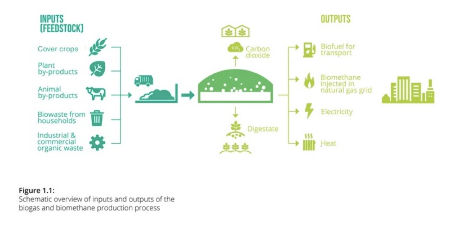
The generated biogas can either be utilized as a cooking fuel or processed further to remove CO2, H2S and moisture content, resulting in a fuel of higher calorific value. If the methane content of the upgraded product is above 96 per cent, it can be used directly as a transportation fuel to replace CNG or injected into gas grids. Another significant by-product of this process is biofertilizer, which can be separated into solid and liquid fragments. This is an excellent soil conditioner and can replace the use of toxic chemical fertilizers. Biogas is an excellent example of developing a circular economy where waste resources are transformed into clean energy and organic fertilizers.
Setting up a CBG Plant: Science and Technology
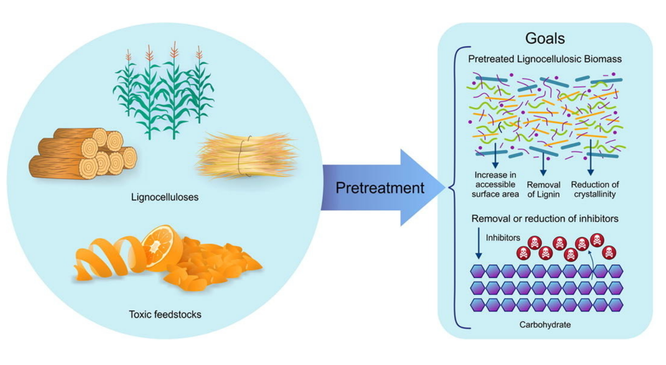
Feedstock Pre-Treatment :
One significant problem with certain types of feedstocks is that they are difficult for microorganisms to break down, or the process of breaking them down is extremely slow. In such cases, pre-treatment methods can be used to eliminate inhibitory compounds and
accelerate digestion. These methods not only increase biogas production, but also decrease the volatile solid content. Pre-treatment methods can be several—physical, chemical, thermal, biological, mechanical, etc.
Mechanical pre-treatment aids in separating different components of the feedstock, grinding solid particles and increasing the surface area. In thermal pre-treatment, the feedstock is subjected to varying temperatures to degrade it. In chemical pre-treatment, strong acids, alkalis or oxidants are employed to break down organic compounds. It is commonly used in the treatment of wastewater sludge and lignocellulosic biomass.
A combination of these pretreatment methods may also be utilized to achieve optimal results. The effectiveness of each method varies depending on the unique characteristics of the feedstock. To transform solid waste into the consistency of a slurry, water is also often added in a specific amount depending
on the nature of the waste material.
Equipment required: Receiving platform, shredders, screw press, conveyor belts, sorting system, grinders, agitators, hydrolysis unit (in the case of agro-waste), pre-treatment tank, feeding tank and feed pump.
Anaerobic Digestion :
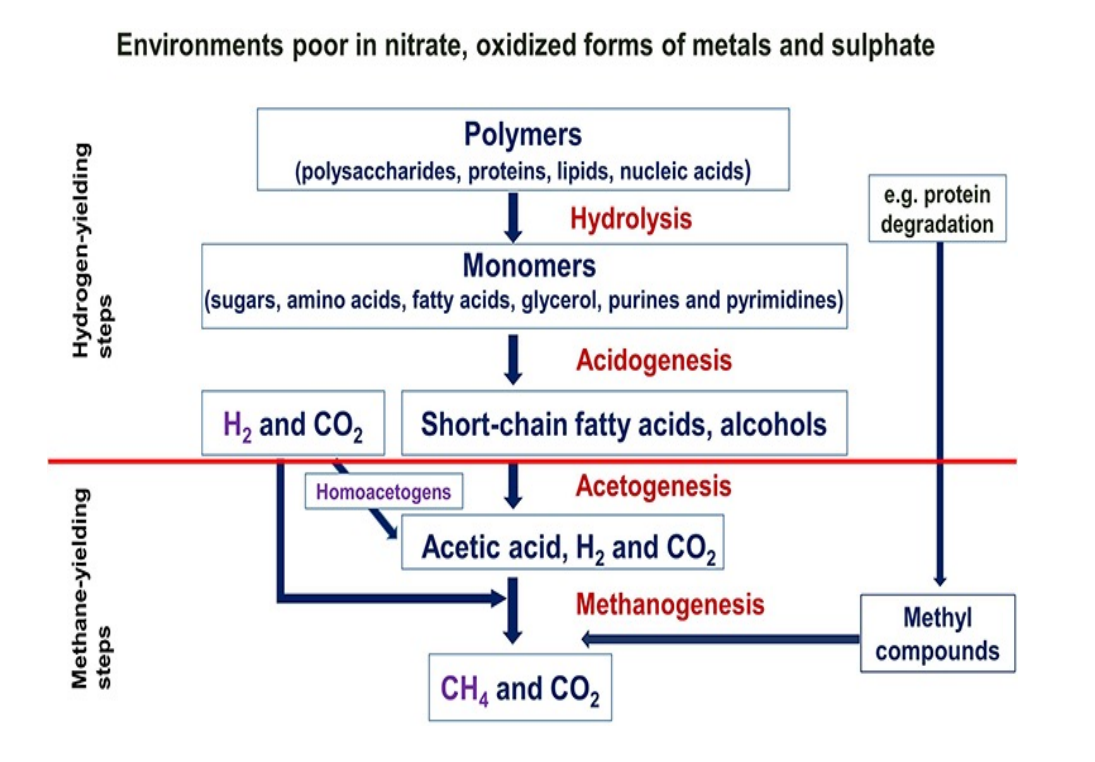
Many different types of anaerobic digesters are available. These vary in configuration, retention time, pre- and post-treatment requirements and operating temperature among other things, depending upon the principal feedstocks being treated. During AD, the breakdown of organic compounds is achieved by a combination of many types of bacteria and archaea (microbes). The biomass added to the digester is broken down into sugars, amino acids and fatty acids (hydrolysis), fermented to produce volatile fatty acids and alcohols (acidogenesis) followed by the conversion into hydrogen, carbon dioxide and ammonia and, finally, methanogens produce biogas from acetic acid and hydrogen.
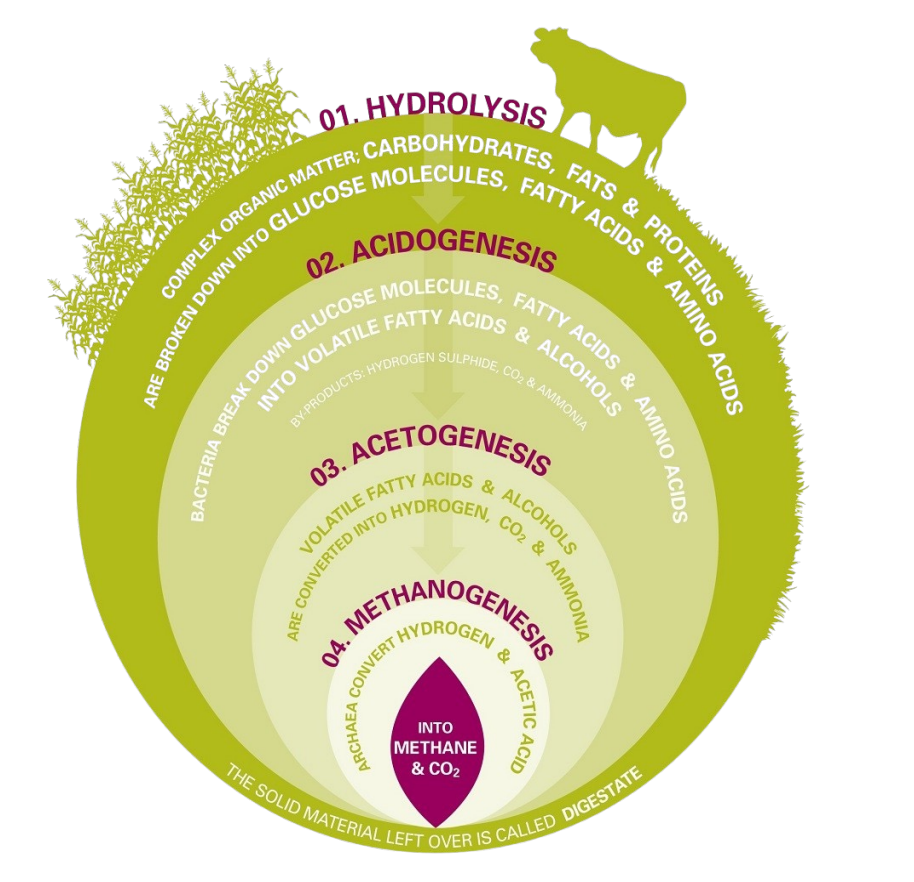
| Step | Description |
|---|---|
| Hydrolysis | Hydrolysis is a chemical procedure that decomposes intricate organic compounds like carbohydrates, fats and proteins into simpler substances such as glucose molecules, fatty acids and amino acids. To alter organic molecules, microbes require them to be soluble. Acid hydrolysis is aided by hydrolase, an enzyme secreted by microorganisms that converts insoluble polysaccharides into soluble molecules. |
| Acidogenesis | Following hydrolysis, bacteria convert glucose derivatives, fatty acids and amino acids into volatile fatty acids (VFAs) and alcohols. |
| Acetogenesis | The volatile fatty acids and alcohols are converted into hydrogen, carbon dioxide and ammonia via the acetogenesis pathway. |
| Methanogenesis | Methanogenesis is the final stage in which archaea—single-celled organisms— convert hydrogen and acetic acid into methane and carbon dioxide. Maintaining the optimal pH range is critical for methanogens. The optimum pH range for methanogens has been found to be between 6.5 and 7.5, and any deviation from this range can cause delays or complete cessation of methane production. |
Hydrolysis Process :
This is essentially the first stage of the digestion process. Water and extracellular enzymes break down the complex polymeric structure of cellulose, starch, proteins and convert them into their respective simple units (monomers or oligomers) such as glucose, fatty acids, and amino acids. The generic hydrolysis reaction is shown in Equation (1), (1)(C6H10O5)n+nH2O→nC6H12O6+nH2(C6H10O5) + H2O→ C6H12O6+ H2 Hydrolytic enzymes generally include amylase, cellulase, lipase, protease, and pectinase. Typically, the growth rate of hydrolytic bacteria is very fast. However, for lignin-rich substrates, the breakdown of polymers turns into the rate-limiting stage. Some compounds in this stage are ready to be converted into biogas, but most compounds need further
breakdown through other stages.
Equipment required: Separate Hydrolysis Tank can be installed for this process
Acidogenesis Process:
The products of hydrolysis are further broken down in the acidogenesis stage by acidogenic bacteria. Hydrolytic products are mainly transformed into short-chain volatile fatty acid (VFA) (acetic acid, propionic acid, formic acid, and lactic acid), alcohol (ethanol, methanol), and ketones (glycerol and acetone). CO2, H2, NH3, alcohols, and trace amounts of other
products are also generated as by products.
Some products, such as CO2, H2, acetate, and formats, are readily usable by the methanogens at the last stage.
Other products need to be further decomposed for the methane production stage. Acidogenesis is generally a very fast process, and there is a risk of VFA accumulation in the digester, resulting in digester toxicity if not properly controlled.
Equations (2)–(4) illustrate the chemical reactions in the acidogenesis stage.
(2) C6H12O6↔2CH3CH2OH+2CO2C6H12O6↔2CH3CH2OH+2CO2
(3) C6H12O6+2H2↔2CH3CH2COOH+2H2OC6H12O6+2H2↔2CH3CH2COOH+2H2O
(4) C6H12O6→3CH3COOHC6H12O6→3CH3COOH
Acetogenesis Process:
Acetogenic bacteria transforms the products of the acidogenesis stage and some of the long-chain fatty acids from the hydrolysis stage into acetate, CO2, and H2. Reactions in the acetogenesis stage are not thermodynamically spontaneous if the partial pressure of H2 is
higher than 10−4 atm. Nevertheless, methanogenic bacteria lower this partial pressure by consuming the produced H2. This syntrophic relation, where some bacteria are fed from other bacteria’s products, makes the acetogenesis stage thermodynamically feasible.
This interspecies H2 transfer is synonymous with electron transfer as H2 is essentially a proton (H+) with an additional electron. The rate of this electron transfer can significantly influence the overall digestion rate.
Equations (5)–(7) illustrate the chemical reactions in the acetogenesis stage.
(5)CH3CH2COO−+3H2O↔CH3COO−+H+HCO3−+3H2CH3CH2COO−+3H2O↔CH3COO−+H+HCO3−+3
H2
(6)C6H12O6+2H2O↔2CH3COOH+2CO2+4H2C6H12O6+2H2O↔2CH3COOH+2CO2+4H2
(7)CH3CH2OH+2H2O↔CH3COO−+3H2+H+CH3CH2OH+2H2O↔CH3COO−+3H2+H+
Methanogensis Process :
This is the final stage where methane is produced from all intermediate products of the previous stages. This stage is strictly anaerobic as the methanogenic bacteria cannot survive in the presence of oxygen.
CH3COOH (acetate) and H2 are converted into CO2 and CH4 by two different groups of bacteria, such as acetophilic and hydrogenophilic. Acetophilic bacteria convert acetate into CH4 and CO2, while hydrogenophilic bacteria convert H2 and CO2 into CH4.
The reactions in this stage are illustrated in Equations (8)–(10).
(8) CH3COOH→CH4+CO2CH3COOH→CH4+CO2
(9) CO2+4H2→CH4+2H2OCO2+4H2→CH4+2H2O
(10) 2CH3CH2OH+CO2→CH4+2CH3COOH
Equipment required: Continuously stirred tank reactor (CSTR) are most commonly used for the Anearbic Digestion. SCADA (Supervisory Control and Data Acquisition) connected panel system which involves a combination of hardware and software that allows operators to remotely control and monitor multiple devices and systems from a central location. The system
consists of a network of sensors, controllers and other devices that gather data and send it to a central control panel, which is typically connected to a computer or a SCADA system. This system allows operators to monitor and control various processes and components, including temperature, pressure, flow and other critical parameters, and make necessary adjustments in real-time.
Five Anaerobic Digester Parameters :
AD bacteria are sensitive to several process conditions. Some critical process parameters are temperature, pH, organic loading rate (OLR), hydraulic retention time (HRT), C/N ratio, etc., as shown below. Based on the feedstock properties and
surrounding environment, optimization of these parameters controls the efficiency, and speed of the digestion process.
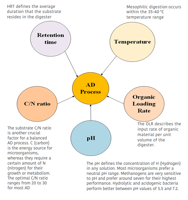
Factors affecting biogas production
List of factors affecting the anaerobic digestion process surrounding environment, optimization of these parameters controls the efficiency, and speed of the digestion process.
| Parameter | Optimum | Description |
|---|---|---|
| Temperature | 35°–38 °C | - Anaerobic organisms are most active within mesophilic (20–45 °C) and thermophilic (45–70 °C) temperature ranges. - When temperature rises, the rate of gas production also increases, but the proportion of methane decreases. |
| Carbon to Nitrogen (C:N) ratio | 25–30:1 | - When the ratio of carbon to nitrogen is high, it indicates low nitrogen content that is not suitable for microbial growth. In such a situation, methanogens consume the available nitrogen for protein production, which ultimately results in carbon wastage and low biogas yield. - If the C/N ratio is low, it can lead to the accumulation of nitrogen and ammonia, which may potentially cause inhibition in the process of anaerobic digestion. |
| pH | 6.5 to 7.2 | In the event that the process causes a reduction in the pH of the substrate within the biodigester, it can be managed by addition of lime. |
| Loading rate | 0.2 kg/m3 of digester capacity | The quantity of feed given to the digester daily is referred to as the loading rate. Both underloading and overloading can lead to a reduction in the production of biogas. |
| Stirring or agitation | 30 rpm, intermitte nt | Agitating the slurry aids in evenly distributing the feedstock and prevents it from settling, ensuring consistent microbial activity. |
| Toxic substances | Nonbiodegrada ble waste | Toxic substances such as ammonia, pesticides, detergents and heavy metals can hinder the fermentation rate since their presence is harmful to microorganisms. |
| Retention Time | Mesophilic: 10–40 days; Thermophili c: 14 days | The time needed for the reactions to complete varies depending on the technology employed, process temperature and waste composition. |
| Solid concentrati on | TS <15% | When the solid concentrations are low, it becomes easier to mix the substrate, which, in turn, promotes the even distribution of nutrients and microorganisms within the digester. Additionally, low solid concentrations can reduce the chances of clogging. |
Biogas Cleaning and Upgrading :
Pollutants in biogas constitute all those gases considered undesirable. Biogas purification process consists of two steps: biogas cleaning and biogas upgrading. The first step involves eliminating harmful or toxic elements like ammonia, hydrogen sulphide, carbon monoxide and siloxanes. The objective of the second step, biogas upgrading, is to increase the energy content of biogas and transform it into a fuel that meets specific standards. Biogas upgrading includes separating carbon dioxide from
methane and drying the gas to eliminate moisture.
Biomethane is the term used for biogas that has been upgraded and contains >95% (v/v) methane. Its composition is very similar to that of natural gas, which makes it suitable for use in the transportation industry and for direct injection into gas pipelines.
Typical Composition of Biogas for Cleaning and Upgrading :
| Component | Chemical symbol | Concentration |
|---|---|---|
| Methane |
CH₄
|
50-75%-vol. |
| Carbon dioxide | CO₂ | 25-45%-vol. |
| Water vapour | H₂O | 2-7%-vol |
| Oxygen | O₂ | <2%-vol. |
| Nitrogen | N₂ | <2%-vol. |
| Ammonia | NH₂ | <1%-vol. |
| Hydrogen | H₂ | < 1%-vol. |
| Hydrogen sulphide | H₂S | 20-20.000 ppm |
| ppm: Parts per million; %-vol.: Volumetric percentage | ||
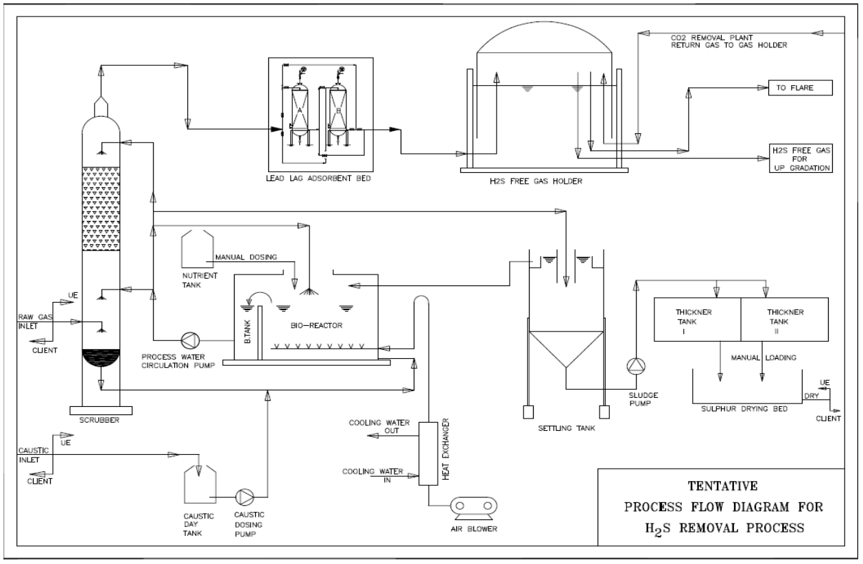
H2S Removal System:
The basic working principle of our H2S Removal System, the Scrubber can be viewed as a caustic type of Hydrogen Sulphide Removal System in which the spent caustic solution is continuously regenerated in a bio reactor.

The scrubbing liquid containing the sulphide is directed to the bio reactor where the sulphide is oxidized by aerobic microorganisms, of the group of the colourless sulphur bacteria, into the elemental biosulphur.

From above equation the hydroxide used in the scrubber is regenerated in the biological step. The liquid entering the scrubber at the top is sulphide free, resulting in high concentration difference between the gas liquid phase. Consequently, very high removal efficiencies, in excess of 99% can be easily obtained. The bleed streamconsisting of sodium salts is sulphide free & can in most cases easily be discharged.
We have developed a nutrient feed as required for the microorganisms which perform the function separation of elemental sulphur from the Hydrogen Sulphide contained in the gas.
The Biogas Desulphuration system with added advantage of elemental sulphur is obtained as bi-product with purity of 80-90%. Sulphur has number of applications various industries; it is used as fertilizer directly or additive to the fertilizers. It is also utilized in making the firecrackers. Its purity can be improved in the range of 95-99% by using the Sulphur smelting process. The sulphur with high purity has special applications in sugar and pharmaceutical industry.
Equipment required: Caustic as per H2s Content in the Raw Material, Scrubbing Tower, Pumps, Biological Culture and Catalyst for Absorption Vessel. Various instrumentations and Instrument Air Compressor
H2S Removal System: Process Flow Diagram
Advantages of Bio-Chemical H2S Removal System :
- Very high H2S removal efficiency – up to 99 %.
- Low cleaning cost of gas as regeneration of caustic.
- Clean technology for H2S removal as sulphur is bi product.
- H2S reduction to less than 100 PPM guaranteed.
- Partial co – absorption of carbon dioxide.
- No expensive chemical required.
- Operation at ambient temperature and pressure.
- Sulphur as by-product with 80 – 90 % purity.
Equipment required: Low Pressure Compressors, DM Water plant, Chiller, Cooling Tower, Scrubber, Stripper, Air Blower and Air Dryer along with various pumps. Various instrumentations and Instrument Air Compressor
Comparison of Various Co2 Removal Systems :
| Parameter | Pressure swing adsorption | Water scrubbing | Membrane separation |
|---|---|---|---|
| Pre-H2S removal required |
Yes
|
Yes | Yes |
| Working pressure (bar) | 14-18 | 6–8 | 14–24 |
| Methane loss | 20–30% | 5–10% | 0.5% |
| Methane content in upgraded gas | >96% | >98% | 97% |
| Electricity consumption (kWh/m3) | 0.25 | <0.20 | 0.25 |
BioCBG Compression and Filling System:
Biogas which has been refined or purified is pressurized at a level of 250 bar, resulting in a type of fuel known as compressed biogas (CBG), which shares similar properties with compressed natural gas (CNG). It is sent to a bottling unit where it is filled and sealed into cylinders. These cylinders are then placed into cascades and transported for storage and sale. CBG is stored at gas filling stations using two commonly used systems: buffer and cascade storage systems. In a buffer storage system, the pressure of CBG is maintained at a consistent level of 250 bar for all reservoir cylinders. In contrast, in the cascade storage system, the reservoir cylinders are kept at varying low, medium and high pressures. CBG can be distributed through pipelines at low (~40 bar), medium (~160 bar) and high (~250 bar) pressures.
The biomethane produced needs to adhere to the following requirements and standards:
1. It must not contain any liquids throughout all the different temperatures and pressures it may encounter within the storage and dispensing system, fuel containers, engine and fuel system, and piped network.
2. It must not contain any particulate matter like dust, dirt and other similar substances.
3. The fuel delivered as biomethane must be odourized to a level comparable to that of the local distribution system.
4. The biomethane intended for use in automotive applications and piped networks must adhere to the requirements outlined in Table 10.
Equipment required: Buffer Vessel, High Pressure Compressors, High Pressure Gas Line and Filling systems, Flow Meters etc Various instrumentations and Instrument Air Compressor
Bio-Fertiliser System:
The semi-liquid residue that is produced from the digester is referred to as bio-slurry. This by-product is an effective fertilizer for crops, as it enhances soil fertility, improves soil structure and increases crop yield. Studies have indicated that bio-slurry may even outperform traditional farmyard manure and may also decrease the need for chemical fertilizers. Additionally, bio-slurry is not harmful to the environment since it is free from weed seeds, unpleasant odours and pathogens.
After the slurry has undergone fermentation, it is separated using a solid-liquid separation device. A portion of the liquid component is combined with humic acid and additional fertilizer components to create a liquid fertilizer. This product is then packaged and sold,
while any leftover water is recycled.
The solid fraction obtained from separation is sent to an extruder or screw press where the fibrous material is compressed to create solid manure. This solid manure is packaged and sold similarly to the liquid fertilizer.
| Parameters | Solid organic fertilizer | Liquid organic fertilizer |
|---|---|---|
| Moisture, per cent by weight |
30–40
|
90–97 |
| Total organic carbon, per cent by weight, Min | 14 | 14 |
| NPK nutrients (Total N, P2O5, and K2O %) | 1.2 | 1.2 |
| C:N ratio | <20 | <20 |
| pH | 6.5 to 8.0 | 6.5 to 8.0 |
| Conductivity (as ds/m), Max | 4.0 | 4.0 |
| Pathogens | Nil | Nil |
| Arsenic (As) | 10 | 10 |
| Cadmium (Cd) | 5 | 5 |
| Chromium (Cr) | 50 | 50 |
| Copper (Cu) | 300 | 300 |
| Mercury (Hg) | 0.15 | 0.15 |
| Nickel (Ni) | 50 | 50 |
| Lead (Pb) | 100 | 100 |
| Zinc (Zn) | 1000 | 1000 |
Equipment required: Solid and liquid separator, aeration tower, entry pump, forced- draught fan, storage tank, compost sewing machine, turners, earth mover, extruder/screw press and mating filling lines.