To ensure the financing of BioCNG projects, extensive support by the government, financial institutions and players in the oil and gas sector is required. Through financial assistance/subsidies and low cost affordable loans, stakeholders and financial institutions are supporting the development of BioCNG ecosystem.
Project Cost – CAPEX andOPEX
The capital expenditure (CAPEX) for a typical 6 TPD BioCNG plant varies from 5.0 Crore to 6.0 Crore which varies based on the type of biomass feedstock and technology deployed.
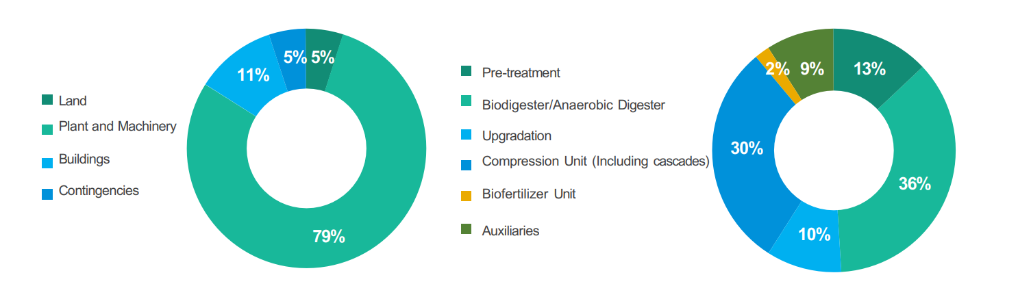
It has been estimated that the plant and machinery costs contributes ~76% of CAPEX and varies with BioCNG production capacity, pre treatment requirements, type of technology used for upgradation etc. A broad overview of the CAPEX cost for an 8-10 TPD BioCNG project in India is given below
Overview of the CAPEX cost break-up
Overview of the CAPEX cost break-up
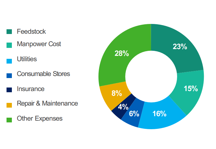
The OPEX cost for an 6 TPD project is generally 4.0 Crores to 5.0 Crores and may vary based on feedstock prices, transportation expenses etc.
OPEX cost basically includes electricity cost, water cost, consumables cost, manpower cost, repairs and maintenance cost, administrative overheads and raw materials/feedstock cost.
A broad overview of OPEX cost for 6 TPD for BioCNG in India is given besides.
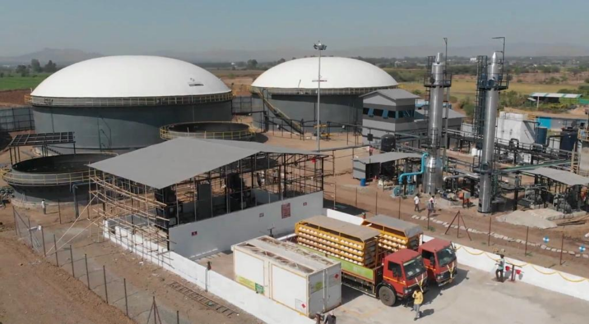
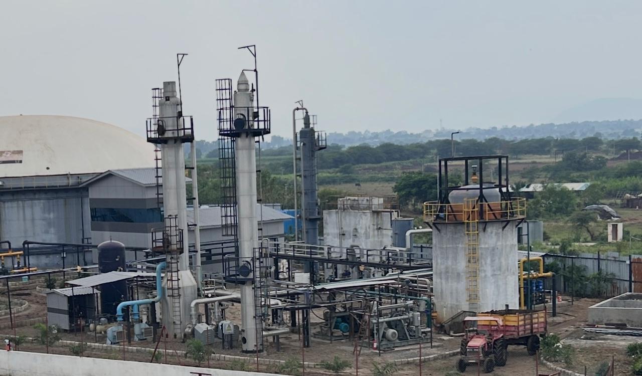
150 TPD Pressmud / 06 TPD BioCBG Plant
Name of the plant: UNITED BIOENERGY PVT LTD
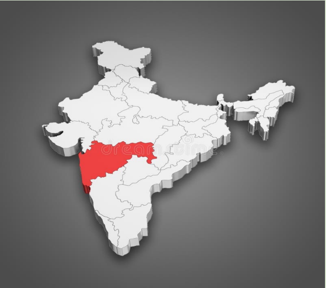
LOCATION: JUNNAR, PUNE
Plant start date:
April 2023
Bio-CNG production
capacity: 6 TPD
Number of digesters: 2
Feedstock used:
Multifeed Digester –
Working on Sugarcane
Pressmud
Daily feedstock
requirement: 150 TPD
Land requirement:
20 acres (Including 1200 Kw
Solar Power Plant)
Biogas purification method: H2s - Bio Chemical absorption & Co2 – Water Scrubbing
Gas offtake method:
Dispensed at nearby CNG
pumps using cascades &
Pipeline Injection at
CGD
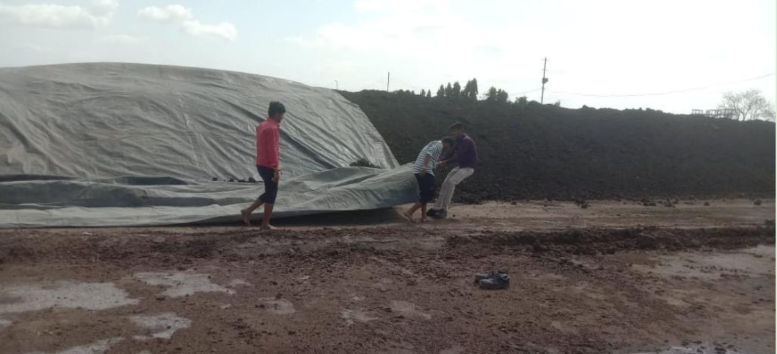
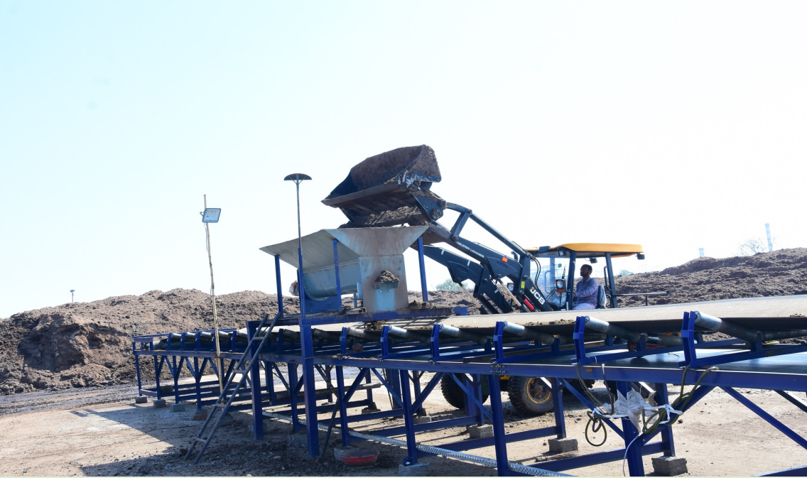
Pressmud is Stored in Pressmud Storage Yard under cover to avoid degradation of the Pressmud so that same can be used through out year during operations.
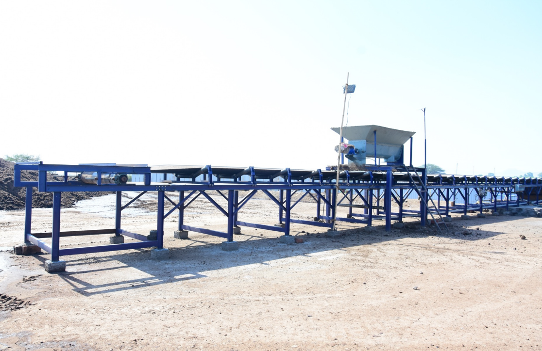
Feeding & Mixing :
Loaders / JCB is being used for the Feeding of presssmud through Screw Conveyer and Belt Conveyer in to Mixing Tank Mixing tank is used to mix the Pressmud and Water as per given ratio which crates homogeneous mixture suitable for feeding in to Digester.
Equipments Required :
1. Loaders / JCB For Feeding 2. Screw Conveyer 3. Belt Conveyer 4. Mixing tank
Biogas Section :
Process :
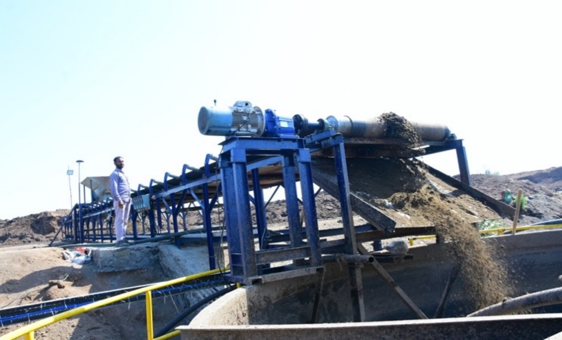
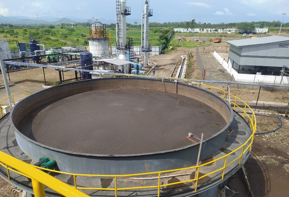
Hydrlysis Tank with Feed Pumps :
After mixing Water / Pressmud homogeneously, same is being fed in to Hydrolysis Tank. Here the Pressmud / Water slurry is being kept for 4-5 days to complete the Hydrolysis process.
India First – Separate Hydrolysis Tank is one
of the First of Its Kind in India where
Hydrolysis Process is separated from
Anearbic Digester
There are Two Distinct Benefits we have observed through Hydrolysis Tank :
A) Factors Affecting – Capacity and
Purification Process
1. Hydrolysis is the first step in the anaerobic decomposition of organic matter which takes place in first 4-5 days. 2. This process is completed outside AD and hence HRT inside AD reduced to 27 Days. 3. This results in increase in Feeding Capacity and eventually output of the plant. 4. Since Co2 is being removed to Atmosphere during these first 4-5 days of Hydrolysis, Methane content in Raw Biogas increased up to 4-5% 5. Eventually Co2 Load on Co2 Scrubbing System reduces and Upgradation Capacity Increased to handle higher qty of Raw Gas
B) Other Operational Benefits
1. After completion of HRT, Digester Slurry is taken out and fed in to Belt Press System. In the belt Press system Polymer is being used for separation of Slurry / Water. 2. This Polymer Mixed Centrate Water can not be re-used directly in the Mixing Tank as it contents Polymer Properties and if same is used as it is, it may result in Solid Deposition inside the Digester Bottom. 3. Feeding through Hydrolysis Tank eliminates the possibility of above solid deposition of solids at bottom of the Digesters. 4. 100% Centrate water removed after belt press can be re-used through hydrolysis tank which results in Lower Consumption of Water. 5. Eventually complete plant becomes ZERO DISCHARGE Pollution free plant.
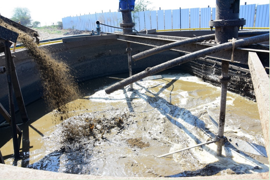
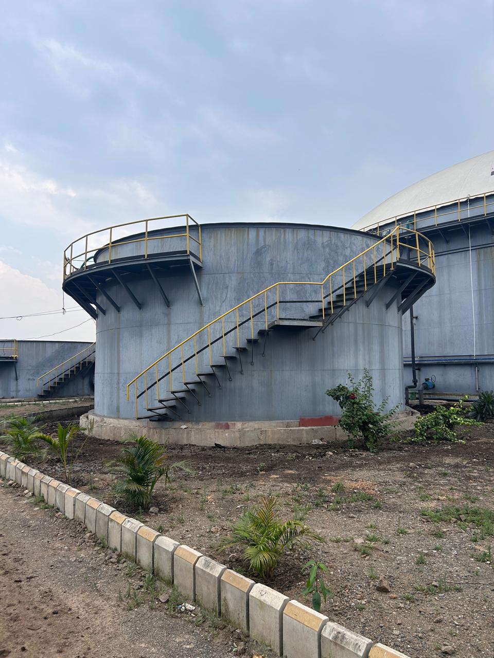
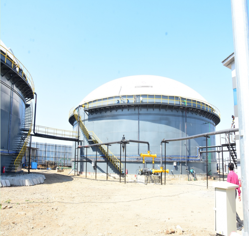
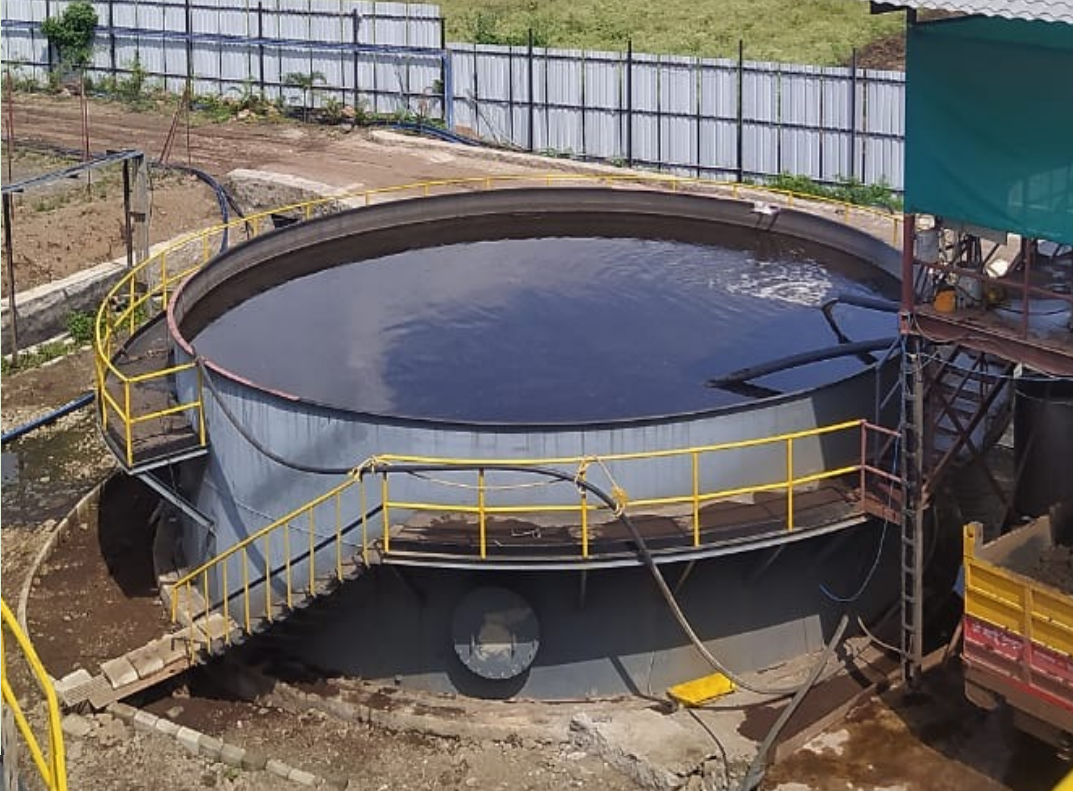
Hydrolysis Tank & Anaerobic Digester :
Process :
Anaerobic Digesters / Sludge Tank / Centrate
Tank with Feed Pumps :
DIGESTERS : After 4-5 days in Hydrolysis Tank, Slurry is being fed into Anaerobic Digesters. The process involves Keeping the Slurry inside Anaerobic Digesters for 25-27 Days HRT to get generate the maximum qty of Biogas. Parameters Maintained at Digesters :
HRT – 25-27 Days
Temp – 35-38 Deg Cent
PH – Up to 7.2
India First – One of the First design of Anaerobic Digester Design without Base Plate for Pressmud Based Digester
SLUDGE HOLDING TANK : After completion of 25-27 Days HRT, slurry is being removed and stores in to Sludge Holding Tank.
This Sludge is then Fed in to Belt Press for Separation of Sold and Water so that Water can be re-used and Solid with Moisture content of approx. 75% Moisture is stored as Fermented Organic Manure.
CENTRATE WATER HOLDING TANK : After Seperation of Solid and Water in the Belt Press, Solid is collected and stored in Fertiliser Storage Yard. And water is being stored in to Centrate Water Holding Tank. From Centrate Holding Tank, centrate water is being fed in to Pressmud/Water Mixing tank for Preparation of Pressmud/Water Feed.
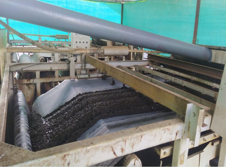
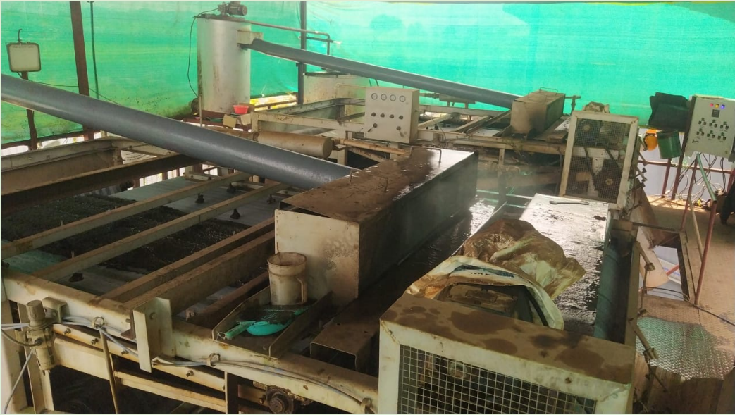
Belt Press / Solid – Water Seperator :
Process :
After completion of 25-27 Days HRT and removal of Biogas, Slurry from Digester is removed and stored into Sludge Holding Tank. The slurry in the Sludge Holding Tank is then fed into Belt Press System for separation of Solid and Water The process involves use of Polymer for solid concentration (As Flocculant Agent) and Belts which separates the Water from the slurry and Solids are separated and collected from the bottom of the Belt Press.
Same is then transported through Tractor Trolleys to Fertiliser Storage Yard.
Belt Press is designed by UBEPL as per requiremet
Biogas Cleaning & Upgrading System : H2S Cleaning System
Process :
Biogas Generated in the Digesters is being stored into Biogas Balloons fitted on the Digesters. The BioGas from the ballons is being fed into Gas Blowers at lower pressure of approx. 15 to 50 mmwc and then Biogas Blowers increased pressure and send to H2S Cleaning System.
H2S Cleaning System :
H2S Cleaning system isBio-Chemical Proess where H2S is removed up to less than 10 ppm and some percentage of Co2 is also removed from the Biogas
Gas Holder & Low Pressure
Compressor:
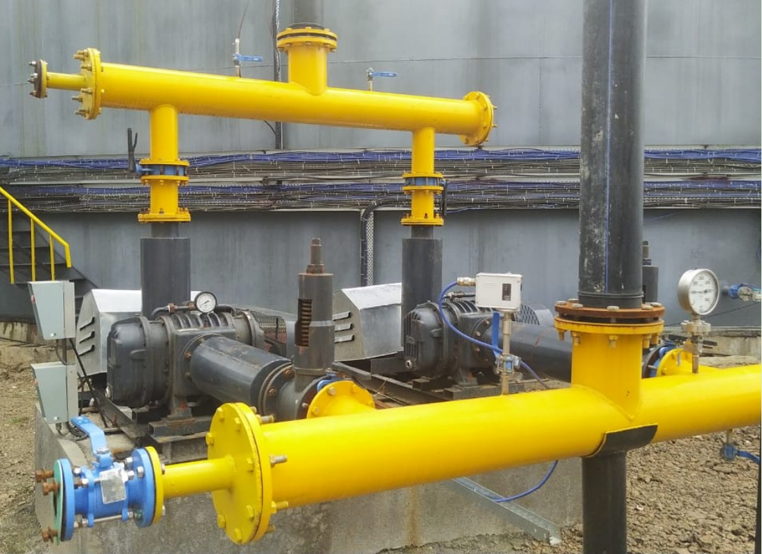
After removal of Co2 Biogas is being fed in to Low Pressure Compressor through Gas Holder to get constant pressure at the inlet of Low Pressure Compressor.
Low Pressure Compressors increases pressure up to 8 Bar for Water Scrubbing process.
Biogas Cleaning & Upgrading System : Co2 Upgrading System
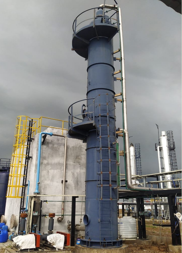
Co2 Scrubbing Column :
High Pressure gas from the Low-Pressure Compressor is being fed into Co2 Scrubber Column for removal of Co2 from the Gas. Here Co2 in the Gas at High Pressure and Low Temperature is dissolved in the water and clean gas is then being send to Co2 Stripping Column.
Co2 Stripping Column :
After desolation of Co2 into Water, the Water is being stripped with Atmospheric Air inside Co2 Stripping Column and Co2 is released into Atmosphere. The water is being reused after stripping of Co2 from the Water.
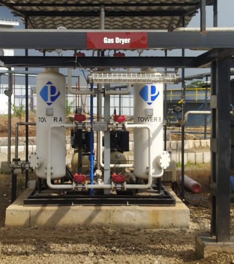
Air Dryer :
After scrubbing water is being passed through Air Dryer so that moisture content in the Gas is removed completely and Dry Gas is being fed to Gas Holder and feeding into High Pressure Gas Compressor.
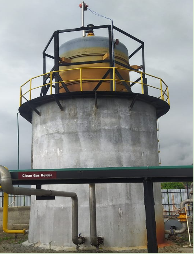
Clean Gas Holder :
After removal of Moisture from the Dryer, clean gas is being stored in the Clean Gas Holder so that High Pressure Compressor can get Constant Pressure and Volume.
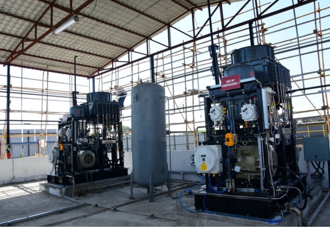
CBG Filling Section
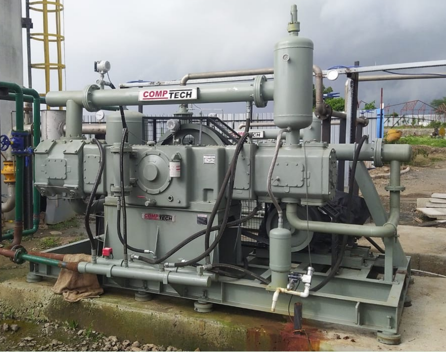
High Pressure Gas Compressor :
After Clean Gas Holder, CBG is being fed in to High Pressure Gas Compressor. Here pressure of the CBG is increased from 7.5 Bar to 230 Bar Pressure. The Gas Qty is measured using Mass Flow Meter which is fed in to CBG Cascades to send it to CNG/CBG Pumps and Injection Facility at CGD.
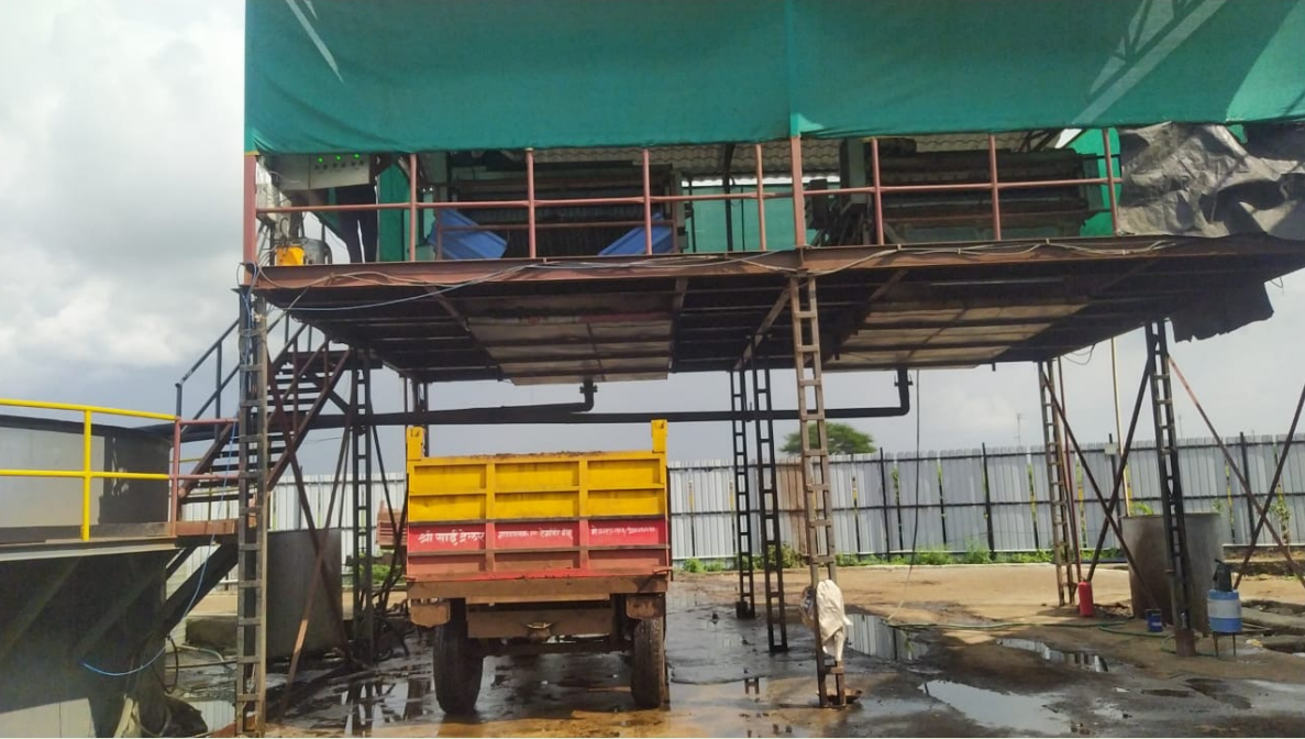
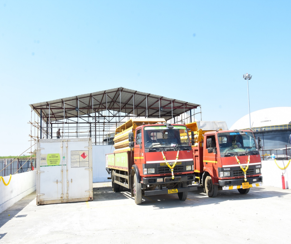
CBG Cascades & Vehicles for Transport :
There are Two Types of Cascades – Type 1 and Type 3 which are being used at our Plant. Type 1 Cascades stores approx. 700 Kgs of CBG and Type 3 Cascades Stores approx. 1500 Kgs Cascades. After completion of CBG Filling at 230 Bar, same are being transported to CNG/CBG Pumps and Injection Facility at CGD.
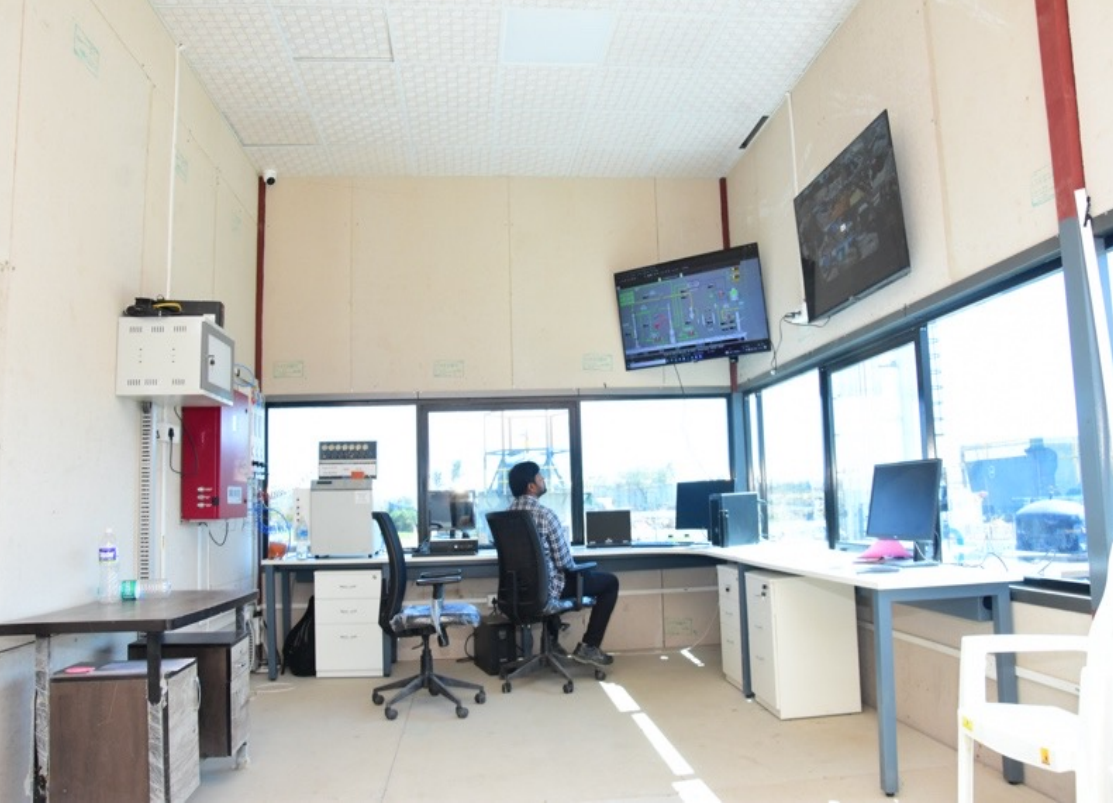
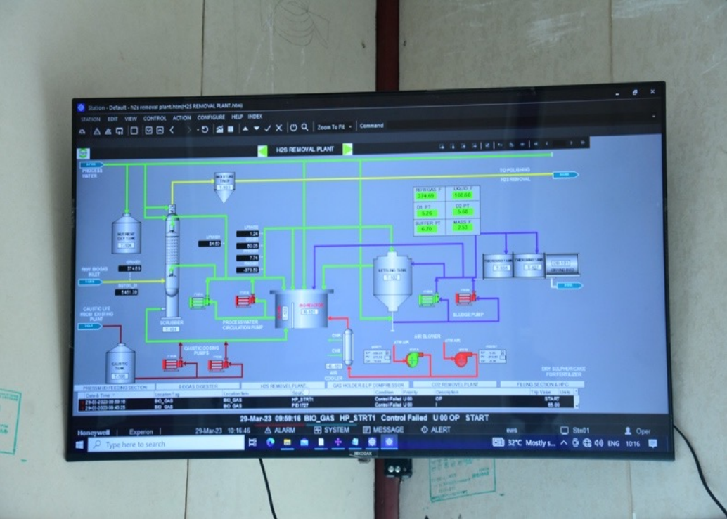
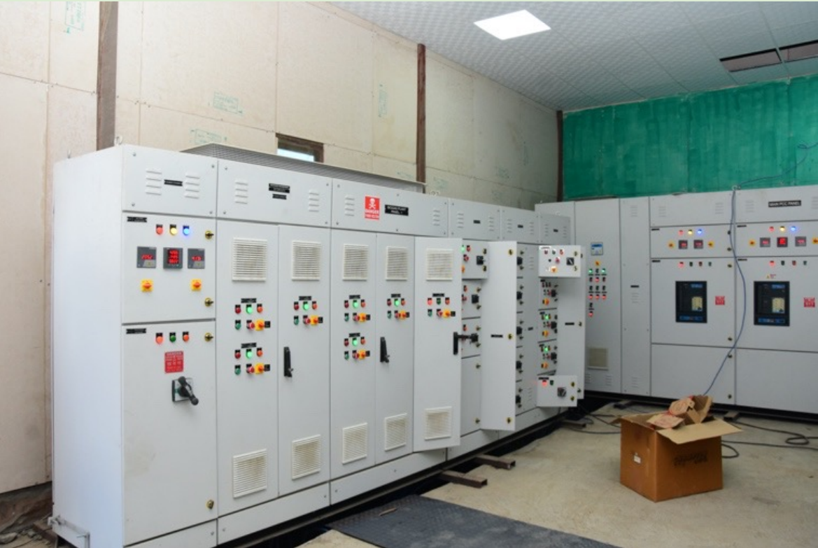
Electrical Systems & PLC / SCADA Automation System :
Complete CBG Plant is being operated with Scada & PLC System from Centralized Control Room